
Cisco Packet Tracer is an essential simulation tool for anyone learning networking. It allows you to design and test network scenarios before deploying them in a live environment. This guide walks you through setting up a simple network consisting of a switch and four personal computers (PCs).
1. Identify and Place Your Devices
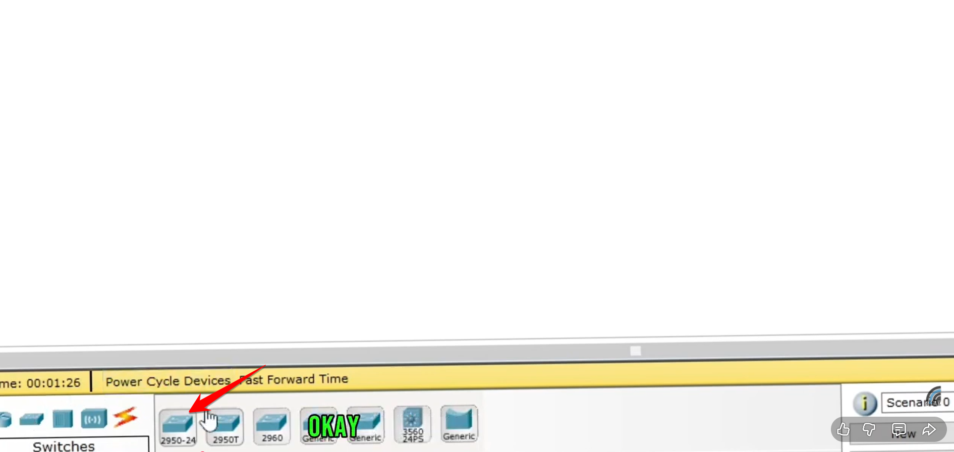
The first step is understanding the component menu at the bottom left of the Packet Tracer interface.
-
Routers, Switches, and Hubs: The first three icons are for routing, switching, and bridging devices.
-
End Devices: Look for the icon that represents end-user devices.
For this lab, you will need:
-
A Layer 2 Switch (e.g., the 2950-24 model).
-
Four End Devices (PC model).
Simply click on the desired device in the menu and then click on the workspace to place it.
2. Connect Your Topology with Cables
Proper cabling is crucial in any network setup. The video clarifies the fundamental cable types:
-
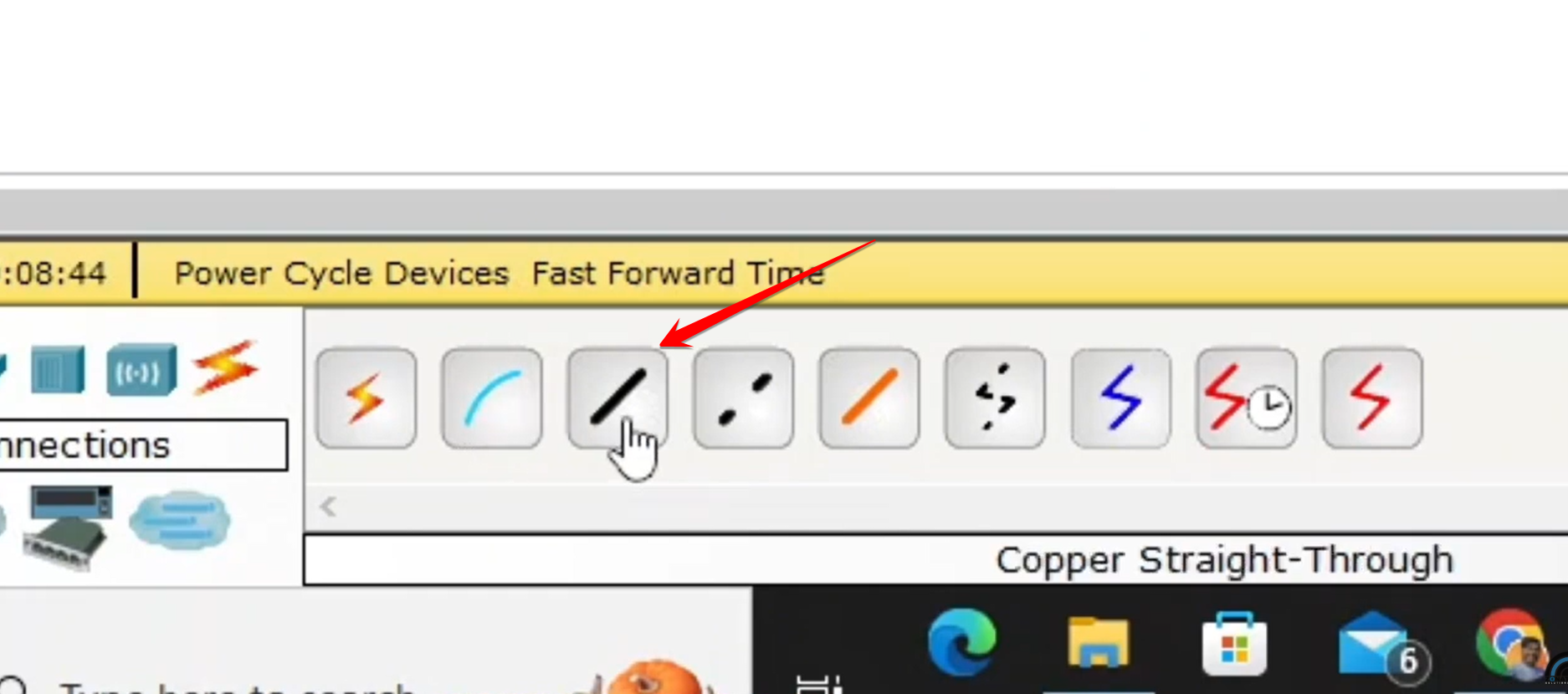
Straight-Through Cable (represented by a solid black line): Used to connect dissimilar devices (e.g., Switch to PC, Router to Switch).
-
Crossover Cable (represented by a dashed line): Used to connect similar devices (e.g., PC to PC, Switch to Switch).
To connect the devices:
-
Click the Connections icon (the lightning bolt ⚡).
-
Select the Straight-Through Cable option.
-
Click on a PC, select
FastEthernet0. -
Click on the Switch, and select a port (e.g.,
FastEthernet0/1). -
Repeat this process until all four PCs are connected to the switch.
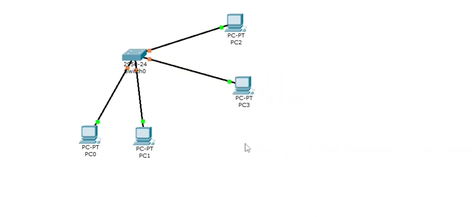 (Note: Switch ports start with an orange light before turning green, which is part of the Spanning Tree Protocol or STP process).
3. Configure Static IP Addresses
For devices in the same local network to communicate, they must have unique IP addresses within the same subnet.
-
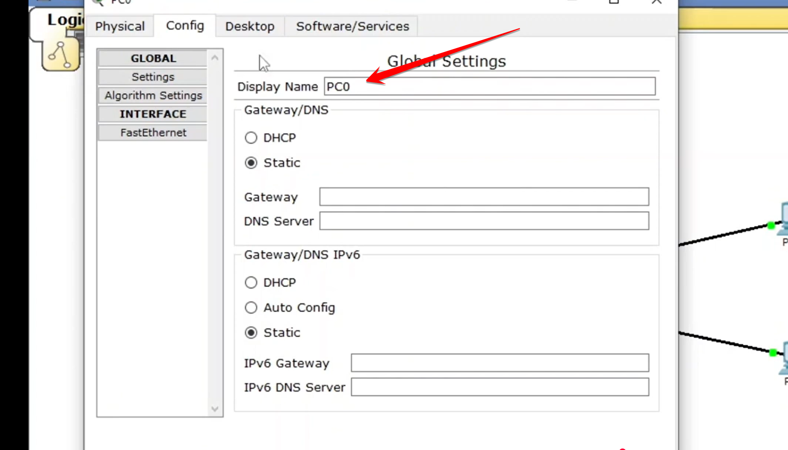
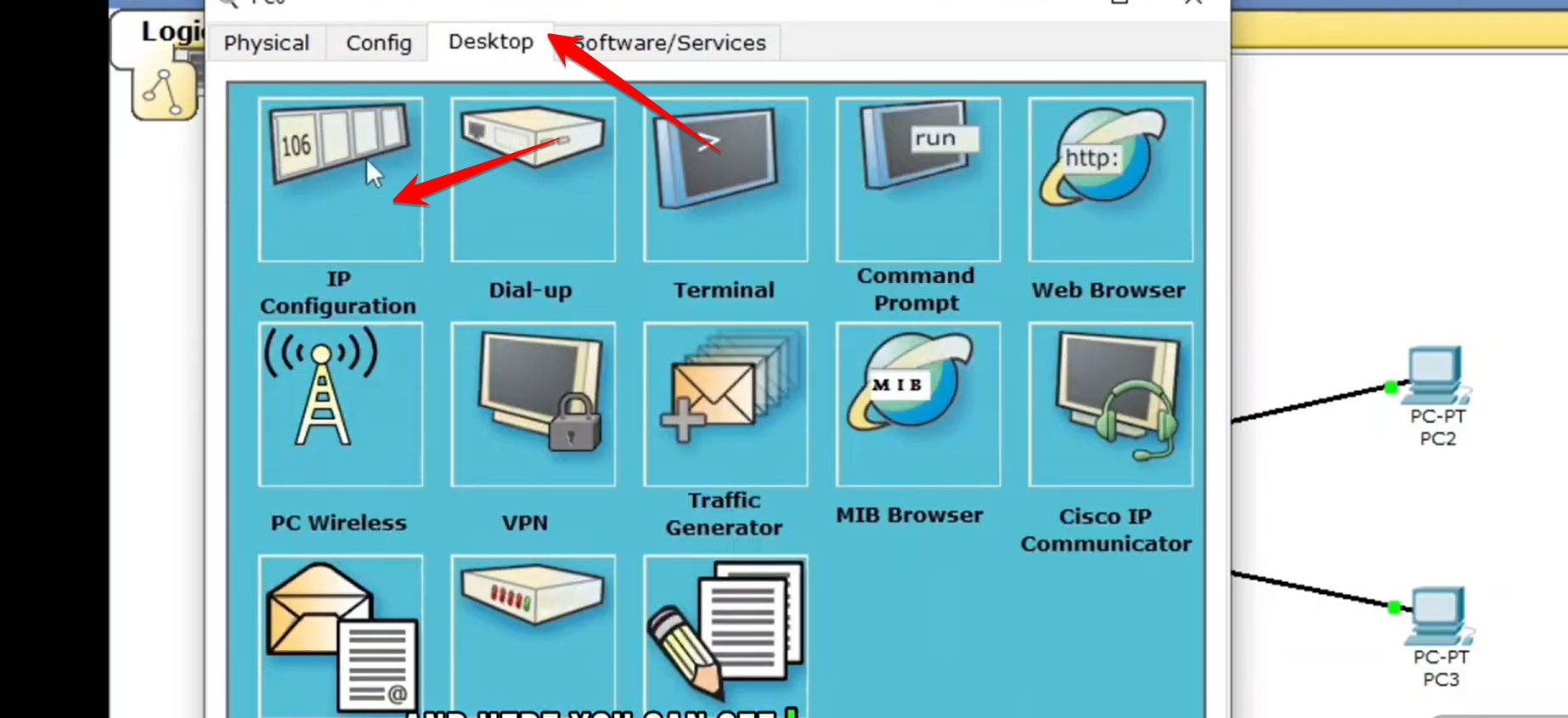
Double-click a PC to open its configuration window.
-
Navigate to the Desktop tab.
-
Click IP Configuration.
-
Set the configuration to Static.
-
Assign the IP Address and Subnet Mask. For example:
-
PC 1:
192.168.1.2 -
PC 2:
192.168.1.3 -
PC 3:
192.168.1.4 -
PC 4:
192.168.1.5 -
Subnet Mask:
255.255.255.0 -
Leave the Gateway field empty as no router has been added yet.
-
4. Test Connectivity (Ping)
The final step is to verify communication between the devices.
-
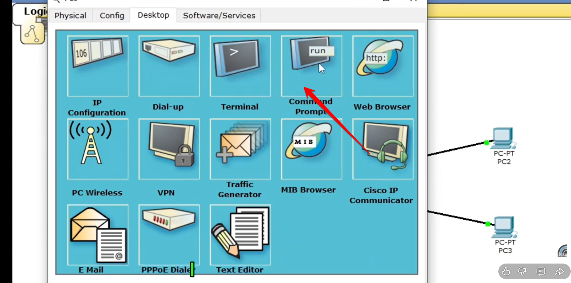
On one of the PCs (e.g., PC 1), return to the Desktop tab.
-
Click on the Command Prompt.
-
Use the
pingcommand to test connectivity to another PC in the lab.-
Example:
ping 192.168.1.5
-
-
A successful test will show a reply, confirming that all devices are correctly connected and configured on the local network.
In future labs, you can expand this basic setup by adding a router to introduce a DHCP server and enable communication with other networks.