
VLANs play a key role in dividing one physical network into several logical ones. They help boost security and overall performance in the setup. This guide shows the steps to set up VLANs. It also covers how to configure switch ports properly as access or trunk types. You can do all this using Cisco Packet Tracer.
Step 01:
Understanding VLAN Basics
You need to grasp the basics of each part before you start configuring anything. That way things go smoother.
The VLAN number serves as the unique ID for the group. It has to match exactly on every switch. Only then can devices in that VLAN talk to each other over the network. This holds true across the whole setup.

The VLAN name just gives a simple label for reference. Think of something like HR for human resources. It makes identification easier in daily use. Still the actual number drives the communication between devices.
In our example here we will set up VLAN 11. It targets an HR network that runs across two different switches.
To create the VLAN on Switch 2 which is SW2 you start in the CLI. Then move into global configuration mode. From there you build the VLAN itself.
Switch# enable
Switch# configure terminal
Switch(config)# vlan 11
Switch(config-vlan)# name HR
Now for Switch 3 or SW3 you follow the same process. Repeat those exact steps on the second switch. This makes sure VLAN 11 shows up there too.
Step 02:
Configure Access Ports for End Devices
An access port on a switch connects to just one VLAN. It handles traffic only for that single group. You use these ports when hooking up end devices. That includes things like computers or printers in the network.
First spot the right port for the connection. Look for the one linked to the PC on SW2. Say it is FastEthernet 0/1 for this case.
Next assign that port to the VLAN you want. Go into interface configuration mode. Then set it as an access port tied to VLAN 11.
Switch(config)# interface FastEthernet 0/1
Switch(config-if)# switchport mode access
Switch(config-if)# switchport access vlan 11.
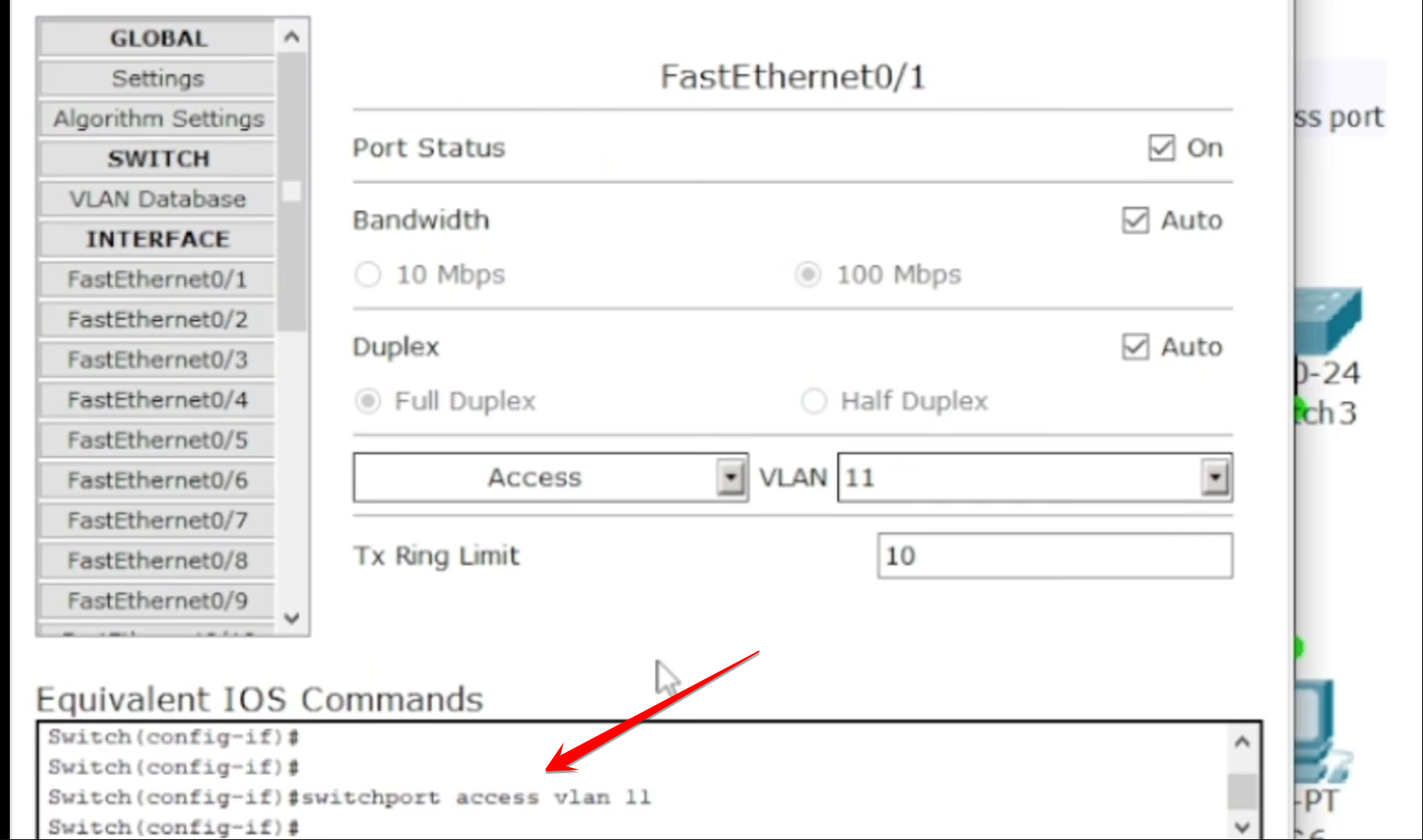
Do the same thing over on SW3. Use those identical commands for the port that links to the other PC.
Step 03:
Configure the Trunk Port Between Switches
A trunk port works like a pathway between two switches. It tunnels traffic from multiple VLANs at once. This lets devices communicate even if they sit on different switches. As long as they share the same VLAN everything flows right. Trunk ports do not tie to just one VLAN on their own.
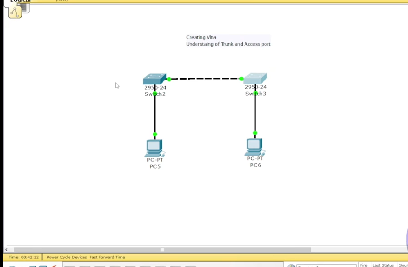
Find the link that joins SW2 and SW3. That would be the inter-switch connection. Assume it is FastEthernet 0/2 in this scenario.
To set it up go into the interface configuration for that port. Then change it explicitly to trunk mode.
Switch(config)# interface FastEthernet 0/2
Switch(config-if)# switchport mode trunk.
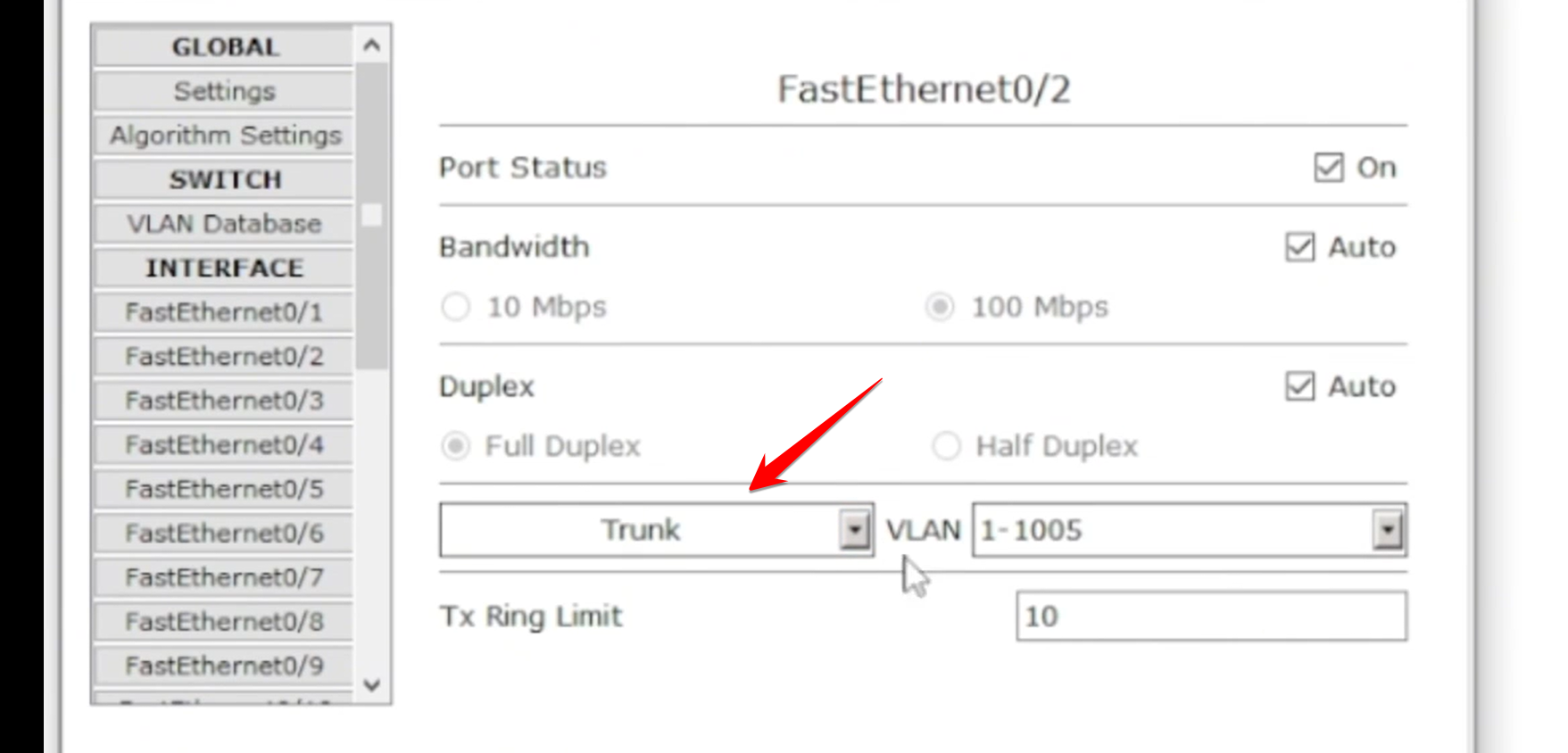
Keep an eye on the STP delay here. The link might turn orange for a bit. That happens while Spanning Tree Protocol handles the change. Once it shifts back to green VLAN traffic starts moving freely between the switches.
Step 04:
Verify Connectivity
Now with access ports set to VLAN 11 and the trunk link ready between switches the two PCs connect logically. They act like part of the same network even on separate physical switches. Communication should work without issues.
Give each PC a static IP from the same subnet range. Try something like 10.10.10.1 for one and 10.10.10.2 for the other.
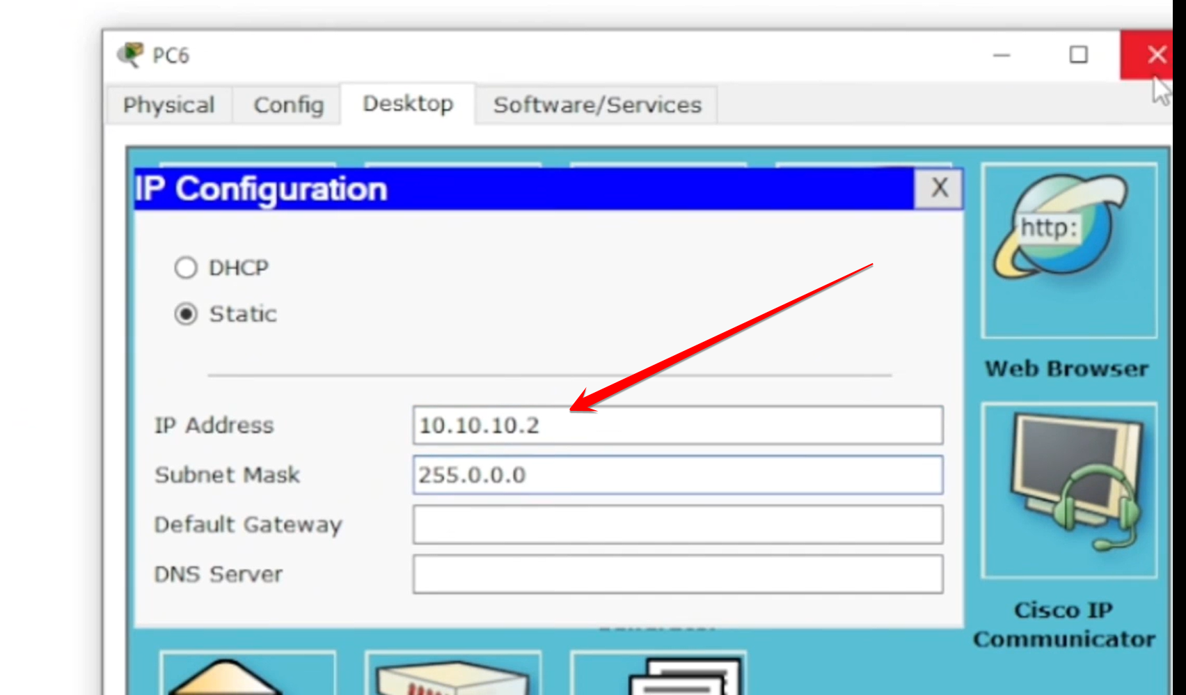
To test it open Command Prompt on one PC. From there ping the IP address of the other PC.
If the ping goes through successfully it means the VLAN setup and trunk link came together right.