The process involves configuring the tunnel on both routers and then bridging the tunnel interface with the local LAN interface.
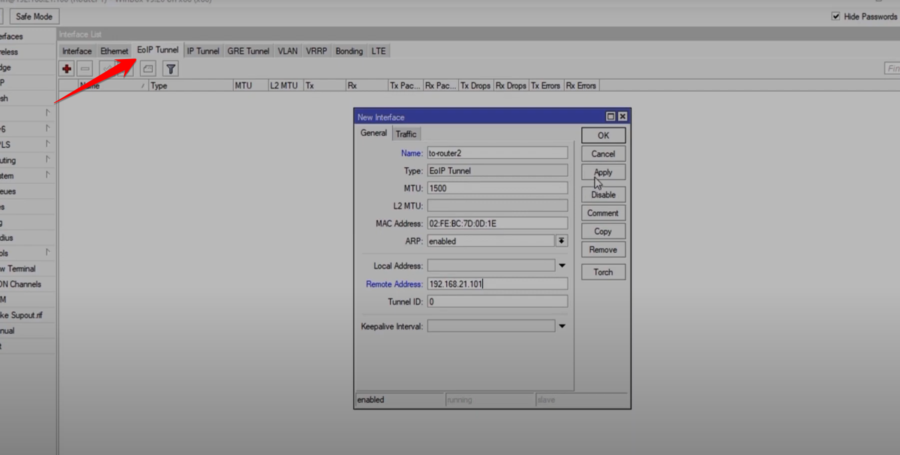
1. Create the EOIP Tunnel Interface
This must be done on both Router 1 and Router 2.
-
Go to Interface and select EOIP Tunnel (click the
+sign). -
Set a descriptive name (e.g.,
to-Router-2). -
Remote Address: Enter the public WAN IP address of the other router.
-
Example: On Router 1, this is Router 2’s WAN IP.
-
-
Tunnel ID: Set an arbitrary ID number (e.g.,
0or100). This ID must be identical on both ends of the tunnel.
2. Create a Bridge Interface
To make the EOIP tunnel function as a Layer 2 extension of your local network, it must be bridged with the LAN port.
-
Go to Bridge and click the
+sign to create a New Bridge. -
Give the bridge a name (e.g.,
Bridge-EOIP).

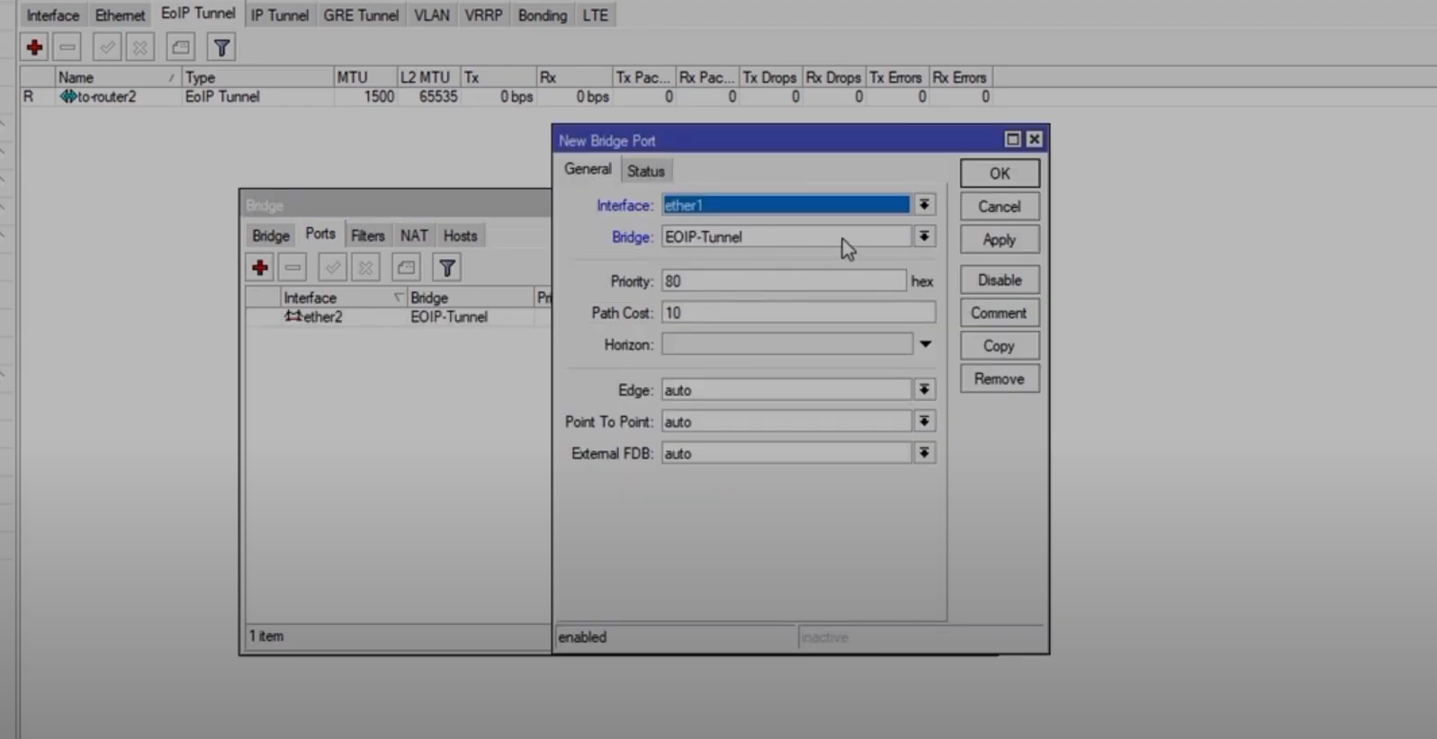
3. Add Ports to the Bridge
Now, add the LAN interface and the new EOIP tunnel interface to the bridge.
-
Go to Bridge and select the Ports tab.
-
Click
+to add a new port. -
Add the Local LAN Interface (e.g.,
ether2/LAN). -
Add the EOIP Tunnel Interface (e.g.,
to-Router-2).
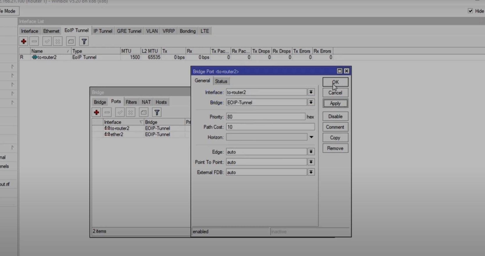
Once this is complete on both routers, devices on both local networks will be able to discover each other via MAC address (Layer 2) and obtain IP addresses from a central DHCP server (if one is configured on the bridged segment).
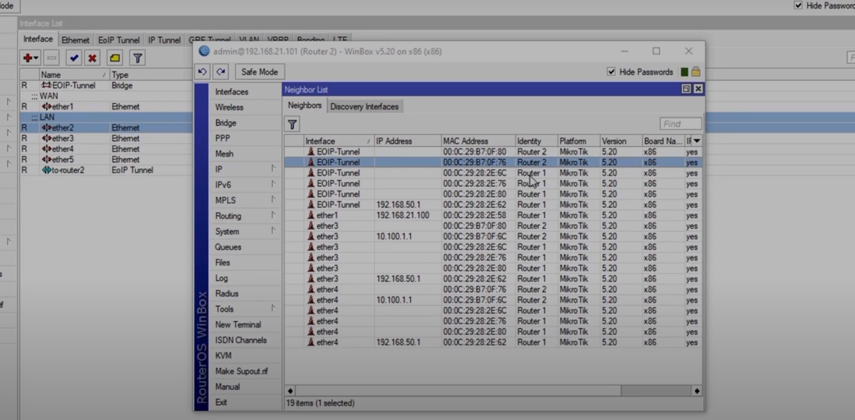
4. Testing the Tunnel
You can test connectivity by checking the Neighbors list in WinBox, which should now show devices connected to the remote router via the EOIP tunnel interface.